English
| Contact Us For Quotation | Email: 464560351@qq.com | Whatsapp&Wechat:+8618620373879 |
INTRODUCTION
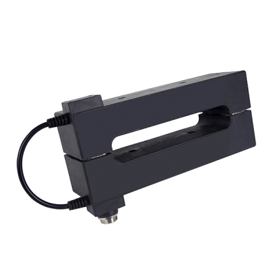
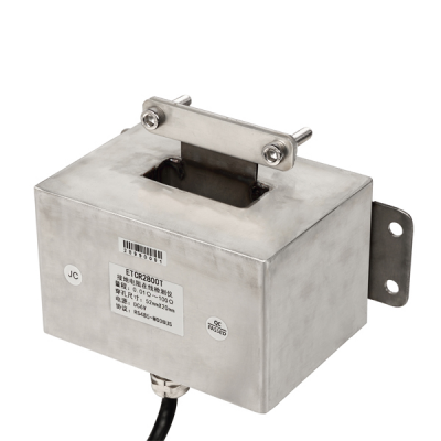
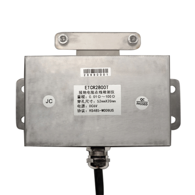
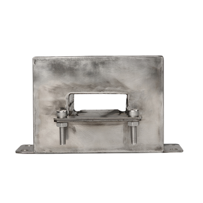
TesterMeter-ETCR2800T Non-contact Earth Resistance On-line Monitor is high-tech product that our company has devoted to "grounding resistance detection technology research" for more than ten years, specialize for online monitoring grounding down lead connection status, circuit grounding resistance and metal circuit connection resistance. On-line testing, non-contact measurement, grounding wire pass through the perforation of the detector, definitely will not influence grounding effective for lightening and normal operation, no need the self-inspection, real time on-line testing. Provide RS485 wire communication (support MODBUS-RTU communication protocol) , The monitor is composed of sensor and PCB module, which is suitable for user secondary development integration. Among them, TesterMeter-ETCR2800T is specially designed for outdoor installation, the sensor housing is made of 304 stainless steel, sealed with internal resin, and has a solid structure. It is anti-explosion and anti-impact, high and low temperature resistant, waterproof and dustproof, all-weather, especially suitable for installation to use of outdoor, oil depot and gas station. TesterMeter-ETCR2800T Non-contact Earth Resistance On-line Monitor suitable for transmission line tower grounding; Meteorological lightning protection grounding; Petrochemical grounding; Communication grounding; Substation grounding; Railway facilities grounding; Construction warehouse grounding; Metal circuit resistance; Electrical equipment grounding and others place. It can also be used for anti-theft monitoring of grounding wires and metal cables. TesterMeter-ETCR2800T Non-contact Earth Resistance On-line Monitor can install and use singly, and also can set up wired or wireless network system. |
TesterMeter-ETCR2800T Accessories:

Detector
Fix Screw
RS485 Communication Wire
Warranty card/Qualification card
Paper Box
SPECIFICATION
Technical Parameters
| Function | Description |
| Function | Loop circuit grounding resistance on-line monitoring, metal return circuit resistance connection online monitoring, grounding condition monitoring. anti-theft monitoring of grounding wires and metal cables |
| Power Supply | Detector:6VDC~9VDC,50mA Max(external power supply). |
| Resistance Range | 0.01Ω~100Ω |
| Resolution | 0.001Ω |
| Accuracy | ±2%rdg±3dgt(20℃±5℃,below 70%RH) |
| PCB Size | 166mm×56mm×20mm |
| Sensor Size | 160mm×90mm×125mm |
| Sensor Perforation Size | 53mm×20mm |
| Sensor Weight | 2.4kg |
| Overflow Indication | Test data>100Ω, communication send “OLΩ” command |
| PCB Interface | J1:Signal output, power input interface |
| J2:Sensor and PCB interface | |
| Symbol J1 | P+:Power input with positive R+:Signal output with positive |
| P-:Power input ground R-: Signal output with negative | |
| GND:Signal ground, short connect with power input ground (P-) | |
| Symbol J2 | I+、I-Current coil interface U+、U-Voltage coil interface |
| GND:Common ground | |
| Connect Wire | 1pcs ,0.5 meter length (5 core wire) |
| Signal Cable | 1pcs ,1 meter length (5 core wire) |
| Connection Identifier | Red/brown---power supply input anode; |
| Black--- power supply input cathode; | |
| Green---RS485 signal anode; | |
| Yellow---RS485 signal cathode; | |
| White--- grounding wire shield | |
| (power supply input cathode can connects with analog grounding by short circuit connection) | |
| Communication method | RS485 communication protocol(support MODBUS) |
| GPRS communication (optional) | |
| Working Temperature And Humidity | -20℃~55℃; 20%RH~90%RH |
| Shift | Automatic shift |
| Grounding lead Interference Current | Should be avoid |
| External Magnetic Field | <40A/m |
| External Electric Field | <1V/m |
| Single Measurement time | About 0.5 second |
| Working current | 50mA Max. |
| Installation | The ground wire goes through the center hole of the sensor |
| Installation Demand | PCB should install into other protective case |
APPLICATION
Network Structure
Wired Network System (Self -Development Software)
Wired network system through RS485 communication protocol to transmit data, build up by the detector, 【communicator, monitoring software, power adapter, computer (above equipment need the user provide and secondary development) 】and so on, suitable for short-distance 1500 meters grounding resistance monitoring.
Wireless Network System (Self -Development Software)

Wireless network system through GPRS communication protocol to transmit data ,build up by the detector(built-in GPRS transceiver module), 【SIM communication card, monitoring software, power adapter, computer (above equipment need the user provide and secondary development)】 and other components for long-distance ground resistance monitoring., distance is not limited.
Principle & Application
Test Principle
TesterMeter-ETCR2800 Non-contact Earth Resistance On-line Monitor, the basic principle of measuring the grounding resistance is to measure the loop resistance. Firstly sensor send out a drive pulse signal to the measured ground return circuit, then measured ground return circuit responses a pulse electromotive force E, under the influence of electromotive force E will generate current I in the be measured ground return circuit. Sensor measures E and I value, and gets resistance value of be measured ground return circuit through the formula: R=E/I.
Loop Resistance & Metal Loop Connection Resistance Tesing
Loop resistance is a composite value includes A point grounding resistance value, grounding down lead metallic conductor’s resistance value, metal overhead line’s resistance value, connection resistance value (contact resistance) between grounding down lead and metal overhead line, B point grounding resistance value.
If grounding network A and grounding network B up and down are connected together on the ground, Detector measures out the resistance value of metal return circuit is very small in general situation, only few of and less than one Ohm, this is the metal loop connection resistance, as a equipotential resistance, but not grounding resistance. Therefore the detector is much convenient to test metal return circuit connection resistance.
Test Method
Single point grounding system: If between grounding network A and grounding network B haven`t overhead line, and not connect together on the ground, then grounding network A and grounding network B can regard as standalone single point grounding connection. Detector cannot test the grounding resistance of single point grounding system directly, will display “OL” overload symbol. Therefore it needs adding one or more auxiliary grounding electrode, to form multipoint loop circuit.
Three point grounding system: In the following figure, the tested ground pole is A and the other two auxiliary ground pole is B and C. The poles A, B, C are connected together on the ground. In the three ground poles grounding down leads were installed on a detector, can accurately test the ground point A resistance value.
Calculated as follows:
R1=RA+RB//RC-------- (1);
R2=RB+RA//RC-------- (2);
R3=RC+RA//RB-------- (3).
Related Series Model
| Model | CT Structure | Range | Difference |
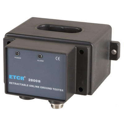
| TesterMeter-ETCR2800B | Close loop | 0.010Ω~200Ω | NO LCD and Indicator light, need to build Internet |
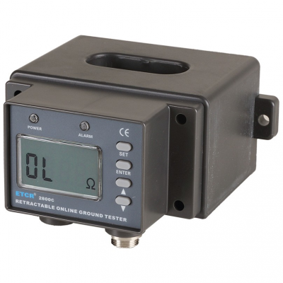
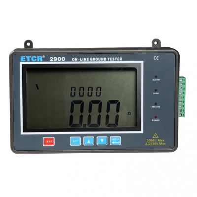
| TesterMeter-ETCR2800C | Close loop | 0.010Ω~200Ω | With LCD, Alarm Setting,Sound and light alarm indication |
| TesterMeter-ETCR2800KB | Split-core | 0.010Ω~100Ω | No need to disconnect the grounding wire in installing,detector with sound and light alarm indication |
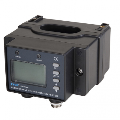
| TesterMeter-ETCR2800KC | Split-core | 0.010Ω~100Ω | No need to disconnect the grounding wire in installing, detector with LCD, Alarm Setting, sound and light alarm indication |
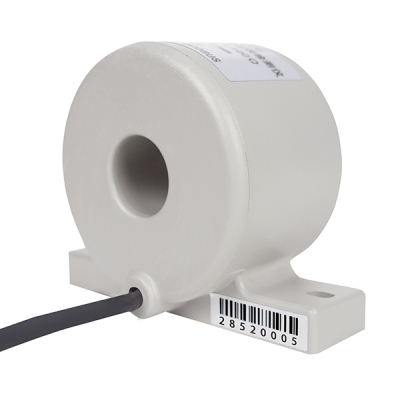
| TesterMeter-ETCR2800N | Close loop and built-in type | 0.010Ω~100Ω | No shell, suitable for secondary development |
| TesterMeter-ETCR2800T | Close loop | 0.01Ω~100Ω | Adopts 304 stainless steel shell, internal filling and sealing with resin, strong structure, anti-explosion, anti-impact, high and low temperature resistance, waterproof and dustproof. |